
It has indeed been clear for some time that in the field of fluid dynamics there is a need to bring a "jumping together" of knowledge, by linking facts and theory across disciplines to create a common groundwork of explanation1. In order to describe the realities of unsteady flow, it is necessary to make three-dimensional, non-intrusive, instantaneous and simultaneous flow measurements of the four fluid variables: temperature, density, pressure, and velocity, sometimes together with body surface pressure/temperature distributions. A new technique has been developed which brings together much of the recent knowledge gained in optical metrology, diffraction theory, luminescence barometry, thin films, and data analysis. A single instrument has been developed, capable of making real-time 3D fluid velocity and near-surface temperature/pressure optical measurements non-intrusively, simultaneously and instantaneously, using a single optical access point. Moreover, the method can potentially be extended to make fluid temperature, density and pressure measurements.
A variety of techniques have evolved to achieve fluid-variable measurement. Many are able to measure intrusively by point measurements, some are basically two-dimensional, while others are three-dimensional and non-intrusive but integrate in one of the three dimensions. In the last few years a lot of successful development effort has been oriented towards measuring the fourth variable: velocity2-5.
Tunnelling Velocimetry originated from a collaboration project with the National Institute of Astrophysics, Optics and Electronics, partly sponsored by the Royal Society, to develop a velocimetry capability in Mexico. Currently, work continues on various aspects of the technique.
A prototype velocimeter is shown schematically in Figure 1. A flow streams along a profile. The flow is seeded with particles, such as polystyrene spheres. A collimated laser beam – typically vertically polarised - introduced into the optical axis of a video detector by a polarisation-sensitive beam-splitter illuminates the flow field. A quarter-wave retarding plate is placed between the polarising beam-splitter and the volume of interest to circularise the polarisation of the illuminating beam on its way to the measurement volume, and also serves to make the particle-scattered light horizontally-polarised on the return path. Thus, the polarising beam-splitter transmits the scattered horizontally-polarised light onto the imaging lens and CCD camera. Hence the name of the technique: it is as if the camera was viewing the particles, from whose motion velocity is derived, inside a lit tunnel. The laser is pulsed and the CCD camera records multiple images of the light scattered back by the seeding particles.
Light power density falling on the particles is lower than for PIV, since power is being distributed over a volume rather than a light sheet. However, the resulting light intensity scattered by the particles in this arrangement is actually higher than for a comparable light-sheet because the efficiency of back/forward scattering is much higher for micron-sized particles. A further advantage of this arrangement is that the drop in power density allows the use of conventional optical components, many of which have a power threshold of 0.1 Joules/cm2. A ½-wave retarding plate is placed in the beam path before the beam-splitter, to be able to adjust the power to be transmitted to the measurement volume, and to provide power level measurement through a photodiode. The flow field images, captured after passing through a filter which excludes all frequencies other than that desired, are then processed through a computer system to extract the motion information. The velocity field can be derived in 3D from the time separation between pulses of light combined with particle positions.
The viewing lens’s characteristics and CCD sensor gain setting give the effective depth of field over which the camera will be able to record particle images. Thus the camera can view a "tunnel" of varying length.
The colour-sensitive beam-splitter in front of the ¼-wave retarder plate is used to separate the fluorescent signal coming from the object, redirecting it to the back-surface parameter-sensing camera6. Pressure/Temperature sensitive paint offers a unique and inexpensive means of determining pressure and temperature distributions, impossible to obtain using conventional measurement techniques at a comparable measurement density6. These paints can be excited either by the TV laser itself, or an external source such as an ultraviolet lamp.
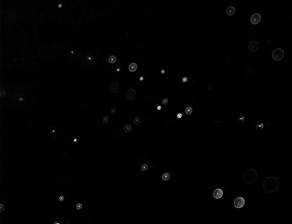
The TV particle image field shows particle diffraction images, which have to be interpreted to obtain particle position in three dimensions. This is quite a challenging step. An accurate analysis of the field preferably relies on Generalised Lorentz-Mie theory7 (GLMT) which is applicable to plane, Gaussian or elliptically shaped incident beams. As part of the collaboration project, a computer program has been developed capable of calculating the particle image, at the image plane of a simplified imaging system including aberrations, due to a plane Gaussian or elliptical wave-front in any illuminated 3D position8. Figure 2 shows a radial intensity comparison between an experimental and a theoretical particle image, with an error of 9.9 grey levels RMS and a positional accuracy of approximately 5 m m at a magnification of 7.5. Such an achievement however, is insufficient to produce a practical system unless the magnification is low, in order to achieve correspondingly large investigation volumes.